
One-Way Fiber Link Troubleshooting: Find the Failed Direction
A one-way fiber fault is a directional problem, not a generic “fiber down” condition. On a duplex link, one transmitter may reach the far-end receiver while the reverse transmitter, return strand or receiver path fails. Label both directions, compare Tx and Rx evidence at both endpoints, and move only one component at a time.
Draw the two optical directions first
Name the endpoints A and B. Then write the paths explicitly:
- Direction 1: A Tx to B Rx through one fiber strand.
- Direction 2: B Tx to A Rx through the other fiber strand.
Do not rely on jacket colors alone. Patch-panel work, polarity changes and undocumented cross-connects can make color assumptions unreliable. The useful question is which transmitter should be visible at which receiver.
If B reports acceptable receive power but A reports loss of signal or very low receive power, light is reaching B while Direction 2 requires isolation. This does not prove that B can decode valid traffic. Nor does it identify whether B's transmitter, the return strand, an intermediate connector or A's receiver is responsible.
A one-direction physical fault can bring down the entire Ethernet link; it does not require one port to remain up. Check the actual alarms at both ends rather than inferring the failed direction from one LED.
Capture four optical readings
When digital optical monitoring (DOM) is available, record A Tx, A Rx, B Tx and B Rx at the same time. Tx means transmit and Rx means receive. Compare each reading with the operating limits for the exact transceiver, not with a generic threshold copied from another model.
The four-reading pattern narrows the search:
- Normal reported B Tx with low A Rx makes the B-to-A path and A receiver priorities, but does not exclude an inaccurate reading or a B transmitter fault.
- Low or absent B Tx points toward the B module, host or transmitter control state.
- Plausible readings on both receivers with no link justify checking speed, optical application, forward error correction (FEC) and port mode; optical signal quality can still be defective.
- Values that change when a patch cord is moved identify a physical-path dependency but not necessarily the original damaged component until the change is repeated.
DOM is diagnostic evidence, not a calibrated acceptance test. Use an optical power meter when accurate path power is required.
Isolate the failed direction without losing the baseline
Check duplex polarity
Verify that each local transmitter is connected to the remote receiver. A Tx-to-Tx and Rx-to-Rx connection prevents the link from establishing. If polarity changed during a cross-connect or patch-panel move, restore the documented mapping before swapping modules.
Inspect and clean the affected path
Follow the approved laser-safety procedure before inspection. Never look into a fiber or optical port; isolate and verify the light source as required before using suitable inspection equipment. Inspect end faces before mating, clean with approved materials and reinspect.
Focus on the direction with abnormal received power, but remember that disconnecting a duplex connector can disturb both strands. The connector-versus-transceiver fault isolation guide explains how to preserve evidence during this step.
Bypass one segment at a time
If operations allow, bypass a patch panel or replace one patch cord in the failed direction with a known-good equivalent. Do not replace both optics and both patch cords together; that may restore service but destroys the evidence needed to prevent recurrence.
Swap endpoints carefully
Use a known-good optic of the same verified optical application and host support, under an approved change procedure. If the fault follows the module, the module becomes the leading suspect. If it remains with the same physical direction, continue along the fiber path and receiver port.
This workflow assumes two separate transmit and receive strands. For single-fiber bidirectional (BiDi) optics, use the BiDi pairing troubleshooting guide and verify complementary Tx/Rx wavelengths instead of applying a duplex-strand swap blindly.
When light is present but traffic is still one-way
An Ethernet interface may show light or even link while traffic fails in one direction. Check input errors, frame check sequence (FCS) errors commonly reported as cyclic redundancy check (CRC) errors, FEC counters where supported, interface discards and remote configuration. If both optical directions are healthy, a forwarding-policy or service-configuration problem may sit above the optical layer.
On platforms using UniDirectional Link Detection (UDLD), capture its state and shutdown reason. Support and normal/aggressive-mode behavior are platform-specific. Do not disable a protection mechanism just to force a port up before the physical fault is understood.
Clear counters only after saving the original values. Then run controlled traffic in each direction and observe where errors first increment. A receiver showing errors is not automatically the source; it may be reporting corruption introduced earlier in the path.
Acceptance criteria after repair
Do not stop when the LED turns green. Confirm stable link state, expected speed and port mode, received power within the exact receiver window and correct Tx-to-Rx documentation. Run controlled traffic in both directions over a defined observation window. Compare new errors and discards with the service's documented acceptance criteria; investigate unexplained CRC or uncorrected FEC events rather than treating a green LED as acceptance. Save the final patch-panel positions and module serial numbers.
Frequently asked questions
Can a duplex fiber link fail in only one direction?
Yes. Duplex transmission uses separate transmit and receive paths. One transmitter, receiver, strand, connector or cross-connect can fail while the opposite direction still carries light.
Should I flip the LC connector immediately?
Only after documenting the current mapping. Reversing polarity is useful when Tx and Rx are crossed, but it will not repair a broken strand, failed transmitter, incompatible wavelength or disabled port.
Is this the same as a BiDi wavelength-pair problem?
No. BiDi uses different transmit and receive wavelengths over one strand and requires complementary A/B modules. Diagnose that topology with the actual Tx/Rx wavelength pair, not a duplex-strand map.
Sources and technical references
- Cisco fiber-link troubleshooting guidance for Catalyst 9000
- Cisco SFP maintenance and troubleshooting guide
- Cisco Catalyst 9500 IOS XE 17.9 UDLD configuration and behavior
Confirm the full optical path before ordering replacements
Share both endpoint models, software, module part numbers, four optical readings, fiber map and the failed direction with Axonode. We can help check whether the replacement BOM preserves the correct application and host compatibility.
Contact Axonode with the two-end link evidence.
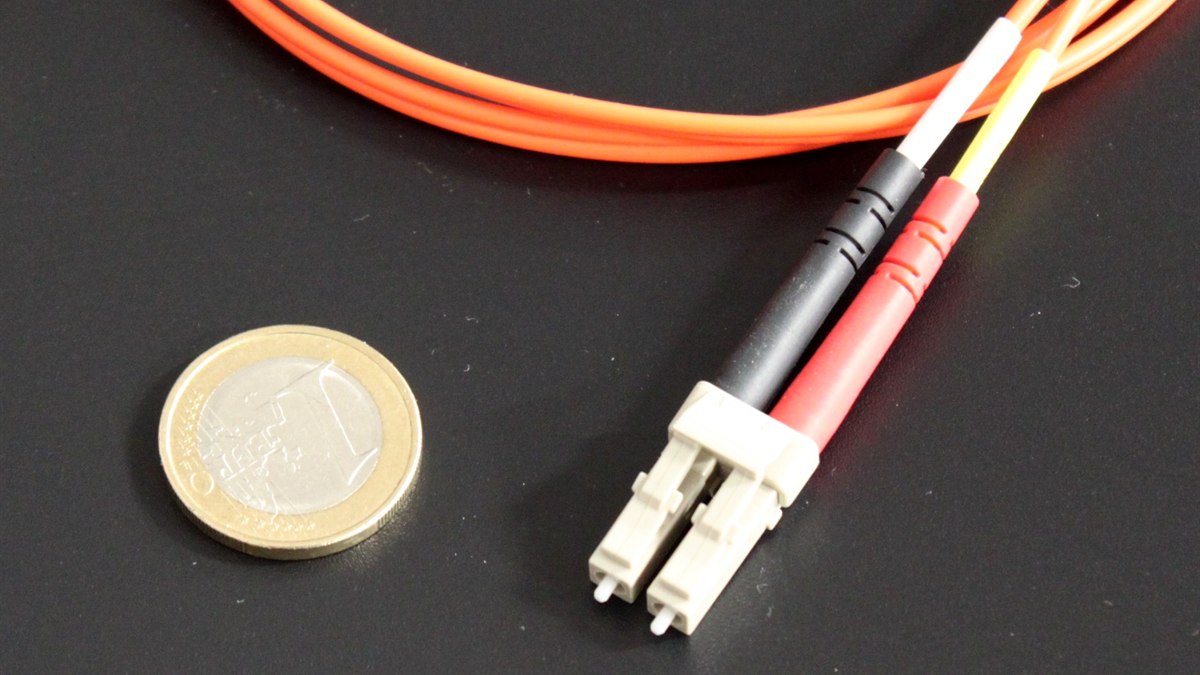
Cover photograph: LC Duplex - 2, Christophe.Finot, CC BY-SA 3.0. Cropped and resized; the adapted photograph remains under the same license. Illustrative duplex connector, not evidence of a failed component.
 One-Way Fiber Link Troubleshooting: Find the Failed Direction
 SFP EEPROM and I2C Read Errors: A Safe Troubleshooting Sequence
 Optical Transceiver EOL Replacement Planning Checklist
 Optical Transceiver Regression Test After a Network OS Upgrade