
Dirty Fiber Connector or Failed Transceiver? Controlled Fault Isolation
Do not replace a transceiver before inspecting the optical path. Microscopic contamination can add loss, reflection or physical damage and can follow a jumper into a replacement module. The safest diagnosis preserves evidence, inspects and cleans correctly, measures each direction and substitutes one verified component at a time.
Save the fault state before touching the link
Record both endpoint platforms, software, ports, module identities, alarms, interface state, error counters and available digital diagnostics. Note the time, recent changes and whether the fault is permanent, intermittent or load dependent.
Save local Tx, local Rx, remote Tx and remote Rx readings. These values help identify the affected direction, although module telemetry is not always a calibrated measurement.
If the host rejects the module or cannot configure the port, resolve that boundary before treating the case as contamination. The SFP detected but link-down guide separates host recognition from optical-path faults.
Inspect before cleaning
Disable the optical sources according to the site's laser-safety procedure before inspection or cleaning. Never look directly into a fiber or module. Use approved inspection equipment and the correct adapter.
Inspect the jumper end face and the equipment-side receptacle with the correct adapter. Look for particles, oil, residue, scratches, chips, pits or burn damage. Inspection before cleaning preserves evidence and prevents unnecessary contact with a clean surface.
Never assume that a dust cap is clean. Caps protect components from handling but can contain contamination.
Clean, then re-inspect
Use the connector-specific approved cleaning method. A common workflow is dry cleaning, inspection and, if contamination remains, an approved wet-to-dry method for that connector followed by another inspection. Do not introduce cleaning liquid into a transceiver receptacle unless its manufacturer explicitly permits that method.
Do not continue cleaning a scratched or burned ferrule as though it were dust. Replace the damaged jumper or follow the equipment repair process. Immediately mate two verified-clean surfaces to reduce recontamination.
Repeatedly moving a dirty jumper among ports can contaminate several transceivers and expand one fault into many.
Recheck the direction-specific evidence
After cleaning, restore the original configuration and compare receive power, alarms and counters with the saved state.
- Receive power improves and the link stabilizes: contamination or a poor mating condition is strongly supported.
- Power remains low in one direction: investigate the remote transmitter, that direction of fiber and the receiver.
- Power appears normal but errors continue: inspect signal quality, reflections, FEC, lane mapping and host support.
- Local transmit power is out of specification: investigate transmitter state, telemetry reliability and the module.
Do not declare the connector clean from a power change alone. Preserve an inspection result when the operating procedure requires one.
Substitute one known-good component at a time
Use a known-good, compatible module or jumper with verified clean end faces. Change only one variable and document the before/after state.
If the fault follows the suspected transceiver to a known-good host and path, module failure becomes more likely. If the fault remains on the original path with a known-good module, the connector, fiber, passive component or port becomes more likely.
One successful substitution is strong operational evidence, but it does not prove a universal compatibility claim. Keep coding, platform and optical application identical during the comparison.
Fault-isolation checklist
- Save identity, diagnostics, alarms and counters at both ends.
- Establish the affected direction.
- Apply laser safety and inspect before cleaning.
- Clean using the approved method and re-inspect.
- Restore the original link and compare evidence.
- Test path loss when telemetry is disputed.
- Substitute one verified component at a time.
- Document the root cause and prevent cross-contamination.
Frequently asked questions
Can dust really take an optical link down?
Yes. Particles can block the core, create an air gap, increase loss or scratch the end face.
Should every connector be cleaned without inspection?
Use the site's approved inspect-clean-inspect process. Inspection avoids unnecessary contact and confirms whether cleaning worked.
Can a dirty connector damage a transceiver?
Contamination trapped between surfaces can scratch them, and high optical power can burn contamination into an end face.
Does normal receive power rule out contamination?
No. Reflection or localized defects can affect signal quality, and diagnostic accuracy varies. Review errors and inspection evidence as well.
When is a transceiver replacement justified?
When exact-module diagnostics, controlled substitution and path checks consistently isolate the fault to that module.
What evidence should be sent with an RMA request?
Include module identity, hosts/software, alarms, power, counters, inspection result, cleaning action and controlled-substitution outcome.
Technical sources
- Cisco: Inspection and Cleaning Procedures for Fiber-Optic Connections
- Cisco: Maintaining Transceivers and Optical Cables
Send evidence, not only a failed-link description
Share endpoint models, software, module part numbers, connector path, inspection findings, power readings, counters and substitution results. Axonode can help coordinate replacement validation and supplier evidence without assuming the optic is at fault.
Contact Axonode for fault-isolation support or review the optical transceiver portfolio.
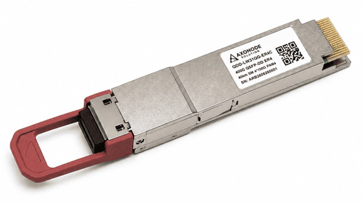 CMIS Module State Troubleshooting for QSFP-DD and OSFP
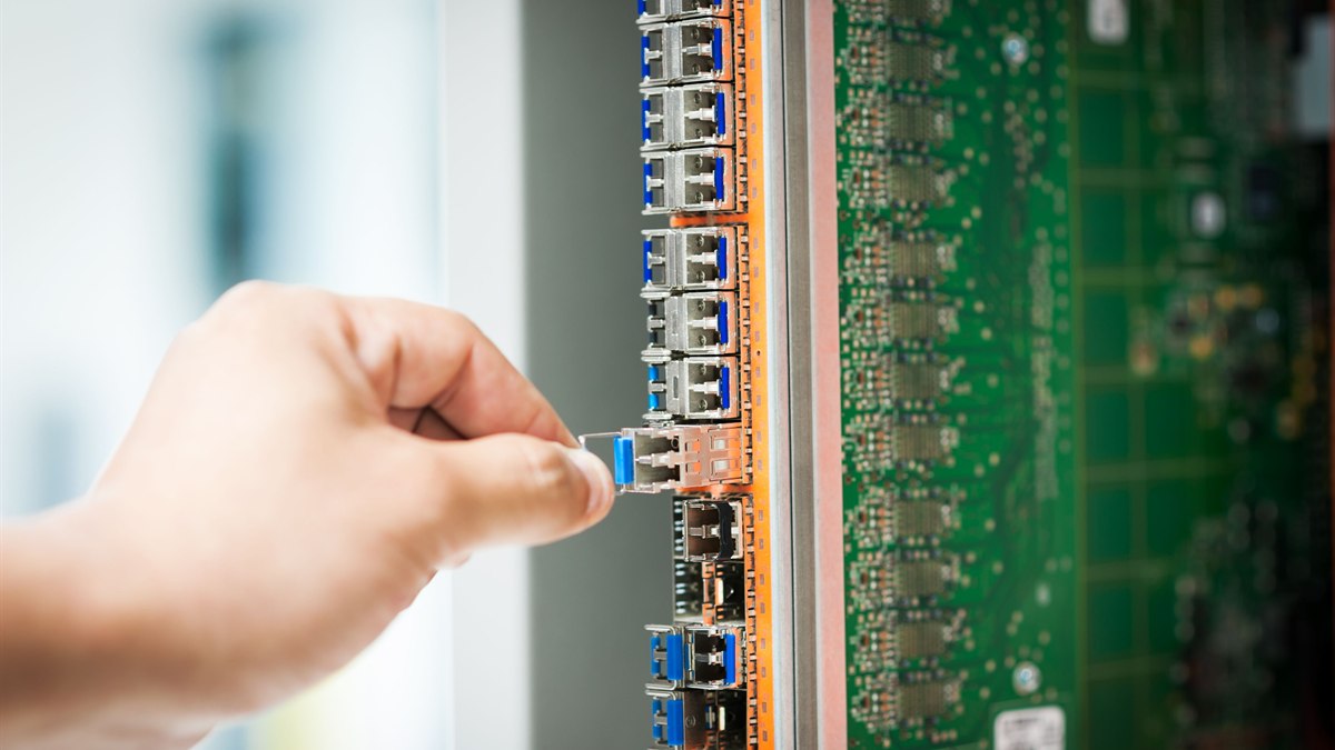 Dirty Fiber Connector or Failed Transceiver? Controlled Fault Isolation
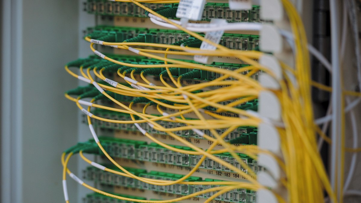 Optical Transceiver Loopback Test: Isolate the Local Port Safely
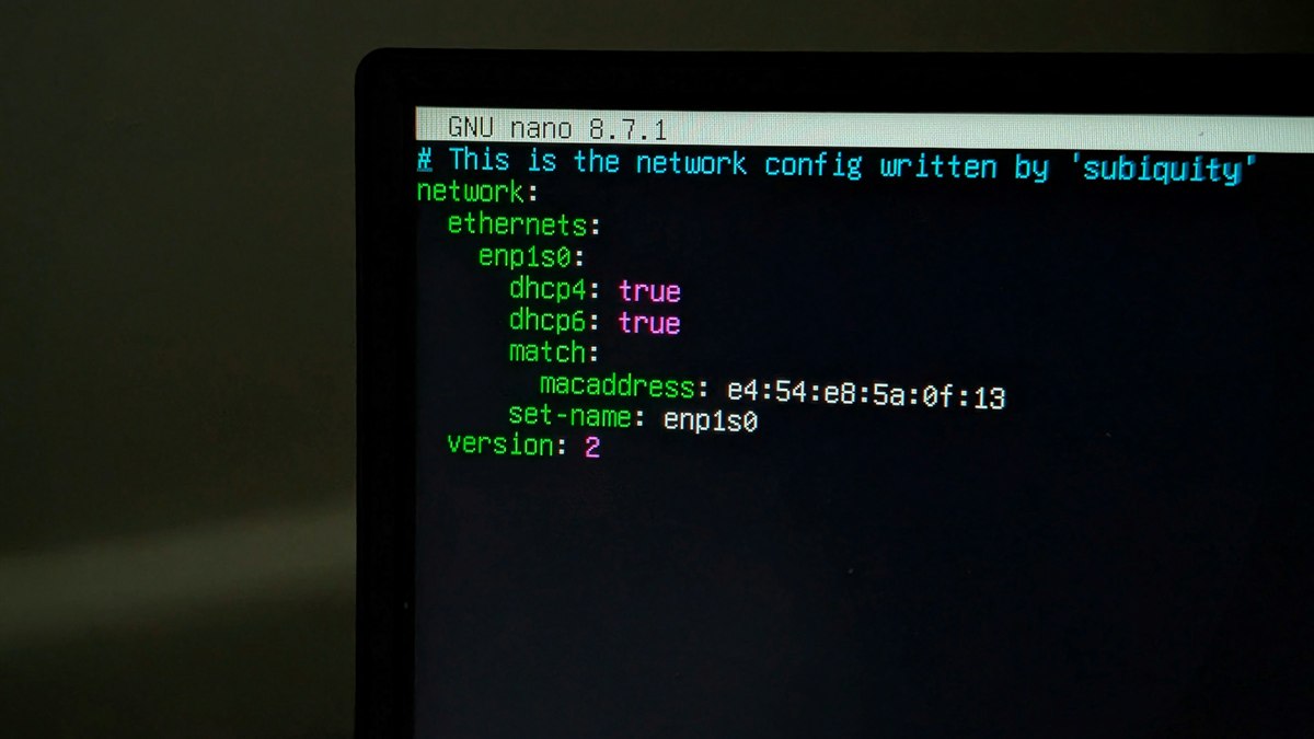 SFP Warning vs Alarm Thresholds: Decide When to Monitor or Act