
MPO Polarity Troubleshooting for Parallel Optics
An MPO connector can be fully seated while the parallel-optics link remains down because transmit fibers do not arrive at the corresponding receive positions. Troubleshooting requires an end-to-end lane map, not a blind cable flip. Verify fiber count, connector gender, key orientation, polarity method and the optical application's active lanes before changing components.
Identify every MPO component
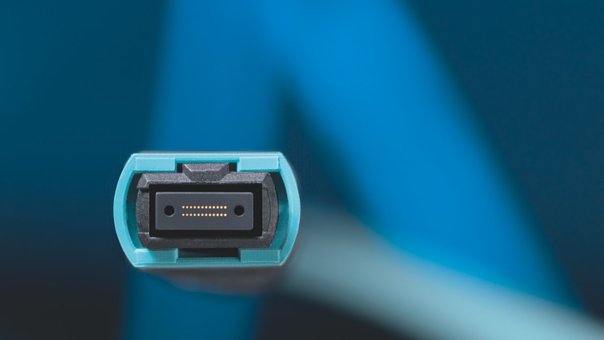
Record whether each plug is pinned or unpinned, commonly called male or female, and whether the interface is UPC or APC. Active equipment often has pinned interfaces and therefore needs an unpinned cable, but the exact equipment documentation controls.
Document Base-8 or Base-12 construction, trunk type, adapters, cassettes, conversion cords and patch cords. A 12-fiber connector used by an eight-fiber optical application can leave center positions inactive. Those inactive fibers are not automatically a fault.
The key and the Position 1 indicator help establish orientation, but they do not alone prove the channel polarity.
Match the polarity method to the application
Polarity exists to deliver every transmitter to the intended receiver. Methods A, B and C use different combinations of trunk, adapter and patch-cord orientation.
Method C pair-flipping is commonly associated with duplex applications and creates operational complexity for parallel optics. Do not assume that a trunk working through cassettes for duplex LC services will directly support SR4, DR4 or another parallel application.
Use the cabling-system design and component records to identify the intended method. If records are absent, test and label the channel rather than inferring polarity from one patch cord.
Build a position-by-position lane map
Start at the transmit lanes of endpoint A and trace each active fiber position to endpoint B. Then trace the reverse direction. Include every cassette, conversion harness and adapter.
Record:
- equipment port and optical application;
- active Tx and Rx positions;
- trunk fiber positions at both ends;
- patch-cord type and orientation;
- remote lane or breakout interface;
- unused positions.
A 400G DR4 link and a 100G SR4 link can both use eight active fibers while differing in fiber type, wavelength and signaling. Similar connector appearance does not make the applications interchangeable.
Inspect cleanliness and physical condition
MPO end faces contain multiple fibers and alignment features. Contamination on one region can affect only one or several lanes. Follow the approved inspection, cleaning and re-inspection process with equipment suitable for the connector.
Never mate two pinned connectors. Do not force a key orientation or use an adapter as a polarity converter unless the component is designed and documented for that role.
Test per-fiber loss and polarity
Use test equipment and reference cords appropriate to the channel and acceptance method. Record loss and polarity for every active fiber, not only aggregate receive power.
If one lane fails, compare its loss, power and path position with the working lanes. If all lanes fail, recheck connector gender, key orientation, trunk polarity and host mode before replacing the transceivers.
The QSFP breakout lane-mapping guide provides related context for host channelization and per-lane FEC, but the physical MPO map remains a separate acceptance item.
Controlled troubleshooting sequence
- Save the host, module and port-mode context.
- Identify Base-8/Base-12, gender, polish and key orientation.
- Determine the intended polarity method.
- Draw the active Tx and Rx fiber positions.
- Inspect, clean and re-inspect both connectors.
- Test polarity and per-fiber loss.
- Change one cord, adapter or cassette at a time.
- Retest every lane and update labels.
Frequently asked questions
Can I fix an MPO link by flipping one connector?
Only if the design calls for that orientation. A blind flip can damage components or create a different lane mismatch.
Are Base-8 and Base-12 the same?
No. They use different populated fiber counts, although the connector body can look similar. Confirm the exact assembly and active positions.
Why do some lanes work while others fail?
Possible causes include one dirty fiber, a damaged position, incorrect lane mapping, a cassette defect or one host lane. Per-fiber testing isolates the difference.
Can two pinned MPO connectors be mated?
No. The cable connected to a pinned equipment interface normally needs an unpinned plug; verify the exact hardware requirements.
Does correct polarity prove the link budget?
No. Polarity only establishes Tx-to-Rx routing. Loss, fiber type, wavelength, host support and FEC still require validation.
What should be included in the BOM?
Specify fiber count, fiber type, gender, polish, key orientation, polarity method, length, application and the interfaces at both ends.
Confirm the lane map before ordering
Share the optical application, endpoint modules, host ports, Base-8/Base-12 infrastructure, gender, polish, polarity method, cassettes, conversion cords and route length. Axonode can help coordinate a technically consistent parallel-optics BOM.
Contact Axonode for MPO path review or review the QSFP breakout lane-mapping guide.
Cover image credit: Reichle & De-Massari via Wikimedia Commons, licensed under CC BY-SA 3.0 DE; cropped for layout.
 MPO Polarity Troubleshooting for Parallel Optics
 Tunable DWDM Transceiver Commissioning Checklist
 QSFP Breakout Lane Mapping Troubleshooting: 4x25G and 4x100G
 LC/UPC vs LC/APC Connector Mismatch: Diagnose and Repair