
LC/UPC vs LC/APC Connector Mismatch: Diagnose and Repair
LC describes the connector form factor; UPC and APC describe different end-face polish geometries. An LC/UPC plug can physically enter an LC/APC adapter or receptacle, but the two polished surfaces should not be mated. The mismatch can create poor physical contact, elevated reflection, excess loss and permanent end-face damage.
Identify polish at every mating point
UPC uses a non-angled, slightly convex physical-contact end face. APC uses an angled physical-contact end face, commonly 8 degrees, designed to direct reflected light away from the fiber core. That benefit depends on two compatible angled surfaces being aligned correctly.
Green commonly indicates APC and blue commonly indicates UPC, but color is not enough for acceptance. Components can be relabeled, old installations can use inconsistent colors and an adapter sleeve does not convert polish geometry. Verify the component specification, part number and visible end face using the approved inspection equipment.
Understand the likely symptoms
A polish mismatch can produce:
- higher insertion loss than the route design;
- unstable or unexpectedly low receive power;
- elevated reflectance or return-loss failures;
- intermittent errors after movement or reseating;
- scratches or damage on one or both ferrules.
The link may still come up, especially if the power budget is generous. Link state is therefore not proof that the mating is correct or safe for continued service.
Reflection-sensitive systems can be affected even when receive power appears adequate. The exact consequence depends on the transmitter, receiver, passive path and application.
Stop repeated mating and inspect safely
If a mismatch is suspected, stop reseating the connectors. Follow the site's laser-safety procedure, remove optical power where required and inspect both end faces with suitable equipment.
Inspection should distinguish removable contamination from scratches, chips, pits or burn damage. Clean only with the approved connector-specific method, then re-inspect before mating. A damaged jumper should be replaced rather than repeatedly cleaned.
Do not look directly into a connector or use an unapproved optical microscope on an energized path.
Trace hidden adapters and passive devices
The visible patch cord may be UPC while an internal pigtail, bulkhead or passive filter is APC. Trace the path through patch panels, cassettes, splitters, mux/demux modules and equipment receptacles.
Document each interface as connector form factor, polish, gender where relevant and fiber type. A purpose-built hybrid jumper can present UPC at one endpoint and APC at the other. That is valid only because each interface still mates like-for-like; the cable does not make a direct UPC-to-APC junction safe.
For WDM routes, the passive CWDM deployment checklist helps document passive components and loss boundaries.
Correct the path, then verify it
Replace the incompatible jumper, adapter or pigtail with the required polish. Inspect, clean and re-inspect all new mating surfaces before connection.
After correction:
- measure or record receive power in both directions;
- compare loss with the route baseline or acceptance limit;
- review errors, alarms and traffic stability;
- repeat reflectance or return-loss testing when the design requires it;
- update labels and the route record to prevent recurrence.
A controlled repair should change the mismatch without simultaneously replacing the transceivers. Otherwise, the result does not prove which component caused the fault.
Prevent the mismatch during procurement
Include connector form factor and polish in every BOM line. “LC” alone is incomplete. For each passive component and jumper, specify the exact interface on both ends, fiber type, wavelength range and required test evidence.
Photographs can help with receiving inspection, but they do not replace the datasheet or physical verification. Keep APC and UPC inventory separated and clearly labeled.
Frequently asked questions
Can LC/UPC and LC/APC be connected temporarily?
They should not be mated. Temporary operation can still create excess loss, reflection or physical damage.
Does a green adapter convert UPC to APC?
No. An adapter aligns connectors; it does not change their end-face geometry.
Is a hybrid LC/UPC-to-LC/APC patch cord safe?
It can be valid when one endpoint requires UPC and the other requires APC, because each connector still mates with the same polish at its own interface. It does not authorize direct UPC-to-APC mating through one adapter.
Why is the link up despite the mismatch?
The remaining power margin may be sufficient for link detection, but performance and end-face safety can still be unacceptable.
Can cleaning fix a polish mismatch?
No. Cleaning removes contamination. It cannot change a UPC surface into an APC surface or repair serious scratches.
Is connector color always reliable?
No. Treat color as a clue, then verify the specification, label and end face.
What should be recorded in the BOM?
Record LC/UPC or LC/APC explicitly for each end, plus fiber type, polarity, length and the connected equipment or passive port.
Technical references
- Fluke Networks: What is an APC connector and how do I test it?
- Fluke Networks: Certifying duplex LC/APC-to-LC/UPC single-mode links
- Cisco: Inspection and cleaning procedures for fiber-optic connections
Confirm every optical interface before ordering
Share the equipment ports, passive devices, connector polish at each mating point, fiber type, route and measured loss. Axonode can help coordinate an optics and patching BOM that keeps the connector path technically consistent.
Contact Axonode for connector-path review or browse MUX/DEMUX solutions.
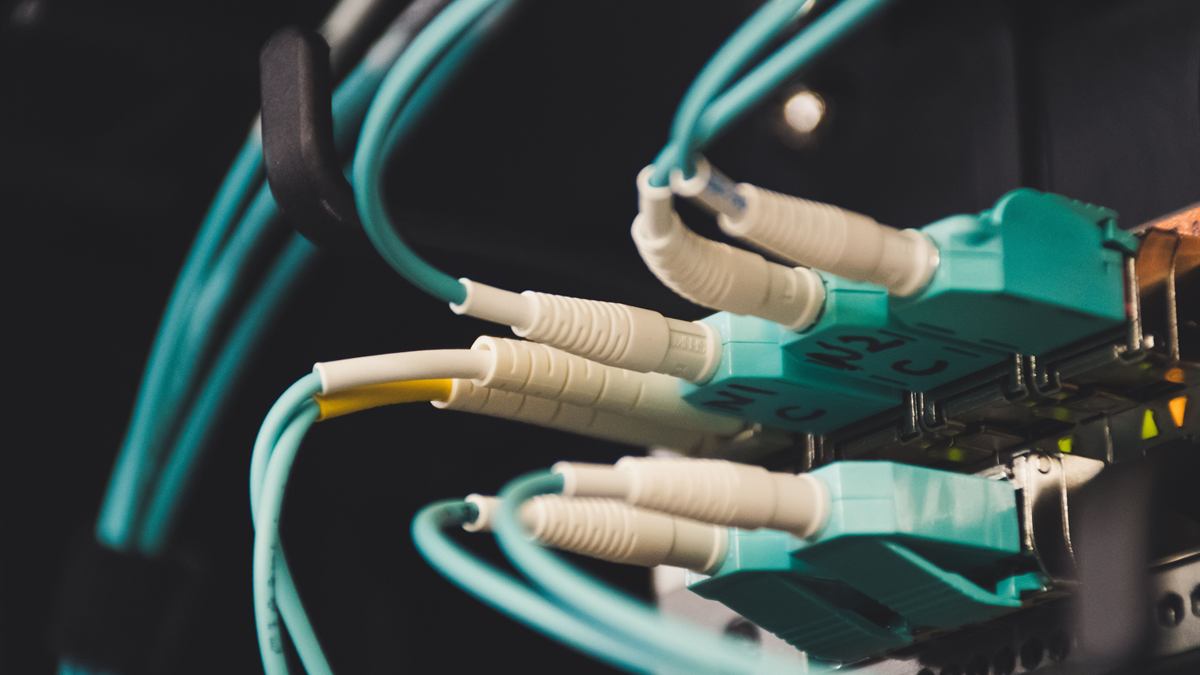 LC/UPC vs LC/APC Connector Mismatch: Diagnose and Repair
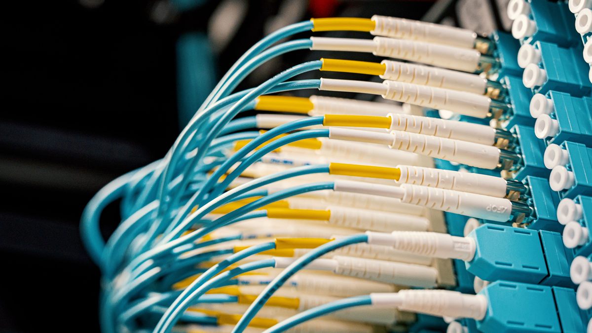 BiDi Transceiver Pairing and Link-Down Troubleshooting
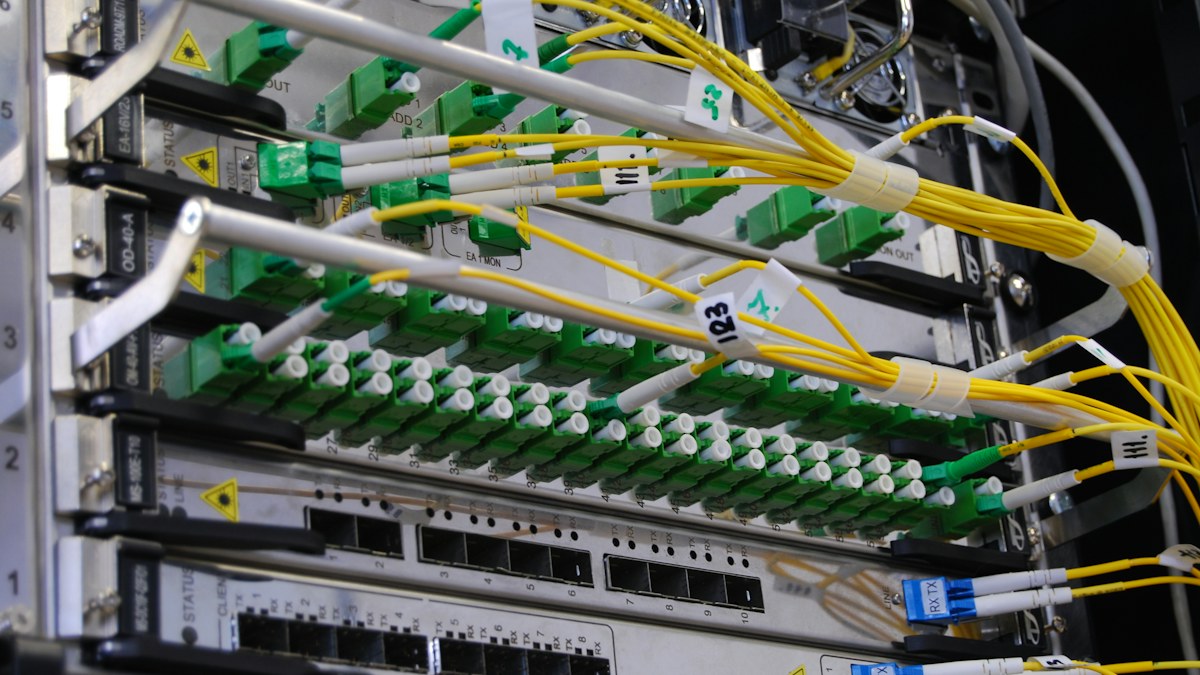 Optical Link Budget Checklist Before Choosing Long-Reach Optics
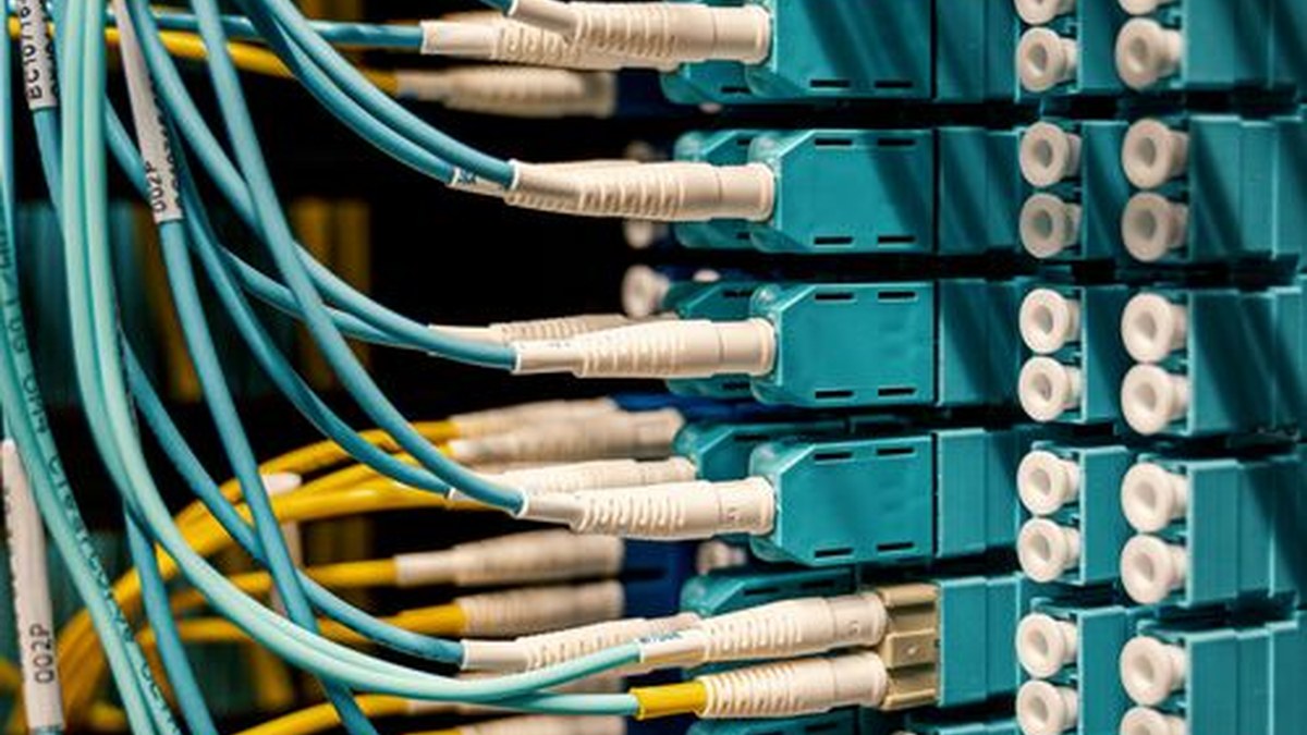 Optical Transceiver Sample Qualification Before a Volume Order