
Optical Link Budget Checklist Before Choosing Long-Reach Optics
Do not select an optical transceiver only because its advertised reach exceeds the route length. A defensible choice must keep received power above the exact receiver sensitivity, below the overload limit and inside an operating margin that accounts for the complete path. The calculation should use worst-case values for the exact modules at both ends.
Record the complete link before calculating
Start with both host platforms, software releases, port modes, data rate, optical application, fiber type and connector type. Record the measured route length rather than a straight-line estimate.
Map every loss-producing element in each direction:
- fiber attenuation at the relevant wavelength;
- connector pairs, patch panels and splices;
- passive mux/demux, optical add/drop filters or splitters;
- conversion or monitoring taps;
- design penalties required by the optical application;
- repair reserve, aging allowance and future patching.
Do not use a generic connector or splice allowance when measured loss or a project standard is available. A route drawing and an optical time-domain reflectometer trace can reveal components that were omitted from the inventory.
Calculate the worst-case available budget
The basic available power budget is minimum transmitter output minus minimum receiver sensitivity. Both are expressed in dBm; the resulting budget is in dB. Use the minimum transmitter value, not the typical value, because typical performance is not a guaranteed design boundary.
Subtract the estimated or measured path loss and applicable penalties from the available budget. The remainder is the design margin. The required margin depends on the operator's design practice, environment, restoration plan and service criticality. Do not copy a universal margin into every project.
Repeat the calculation in both directions. The two endpoint modules can have different transmit ranges, receiver limits or wavelength-dependent losses.
Check receiver overload as a separate boundary
A link can have ample sensitivity margin and still be unsafe because the received power is too high. Compare maximum transmitter output minus the minimum credible path loss with the receiver overload specification.
This check matters when long-reach optics are used across a short, clean path or when amplification is present. If attenuation is required, select and validate it against the exact operating window. Do not assume that an interface remaining up proves the receiver has adequate overload margin.
The detailed receiver overload guide explains how to check the high-power boundary on short or low-loss paths, but the exact power limits must still come from the installed module specifications.
Include penalties that distance alone misses
Reach labels compress several physical limits into one marketing shorthand. Depending on the application, the path may also be constrained by chromatic dispersion, modal bandwidth, reflections, optical signal-to-noise ratio, lane architecture or passive-filter performance.
For WDM routes, include the verified insertion loss of each mux, demux and add/drop stage. For a mixed legacy route, confirm connector polish and fiber type. For parallel optics, verify every lane and the MPO polarity rather than treating the path as one aggregate fiber.
The passive CWDM deployment checklist provides a separate decision framework for channel plans and passive WDM paths.
Validate the calculation during turn-up
Before service acceptance, inspect and clean connector end faces using the site's approved procedure. Measure or record transmit and receive power in both directions. Compare the observed values with the calculated range and save the evidence with the link record.
Digital optical monitoring is useful for trending, but its accuracy depends on the module and host. Use calibrated test equipment when the acceptance plan requires it or when reported values conflict.
Traffic testing, error counters and forward error correction data provide signal-quality evidence. They do not replace the power-window calculation. A quiet link during a short test can still have inadequate restoration margin.
Use this pre-order checklist
- Confirm the exact optical application and host support at both ends.
- Record minimum and maximum transmit power, receiver sensitivity and overload for each exact module.
- Inventory fiber, connectors, splices and passive components by direction.
- Use measured loss where available and document every assumption.
- Add application-specific penalties and the operator's required margin.
- Check both the low-power and high-power operating boundaries.
- Verify dispersion, fiber type, wavelength and connector constraints.
- Plan field measurements, acceptance limits and a rollback option.
Frequently asked questions
Is rated reach the same as optical power budget?
No. Rated reach assumes a defined optical application and path. Power budget is calculated from the exact transmitter, receiver and route losses.
Should typical transmit power be used in the design?
Use the guaranteed minimum for sensitivity margin and the guaranteed maximum for overload analysis unless an authoritative design procedure specifies otherwise.
Does a positive calculated margin guarantee the link?
No. The calculation can omit dispersion, reflections, lane mapping, FEC, host support or an undocumented passive component. It is a planning gate, not universal proof.
Can DOM readings replace an optical power meter?
Not in every acceptance plan. DOM is valuable operational evidence, while calibrated measurements may be required for disputed loss or formal commissioning.
Do I need to calculate both directions?
Yes. Endpoint specifications, wavelengths and route behavior can differ by direction, especially on BiDi or asymmetrical WDM links.
When should an attenuator be considered?
Only when the high-power calculation or measurement approaches the exact receiver overload boundary. Select the value from the verified operating window and retest the link.
Technical sources
- Juniper Networks: Calculate the Fiber-Optic Cable Power Budget
- Cisco: SFP Modules for Gigabit Ethernet Applications Data Sheet
Confirm the route before ordering optics
Share the endpoint platforms, software, optical application, route drawing, fiber type, connectors, passive components, measured loss and required margin. Axonode can help coordinate a project-specific optics BOM and validation plan through vetted OEM manufacturing and testing partners.
Contact Axonode for an optical link review or browse the optical transceiver portfolio.
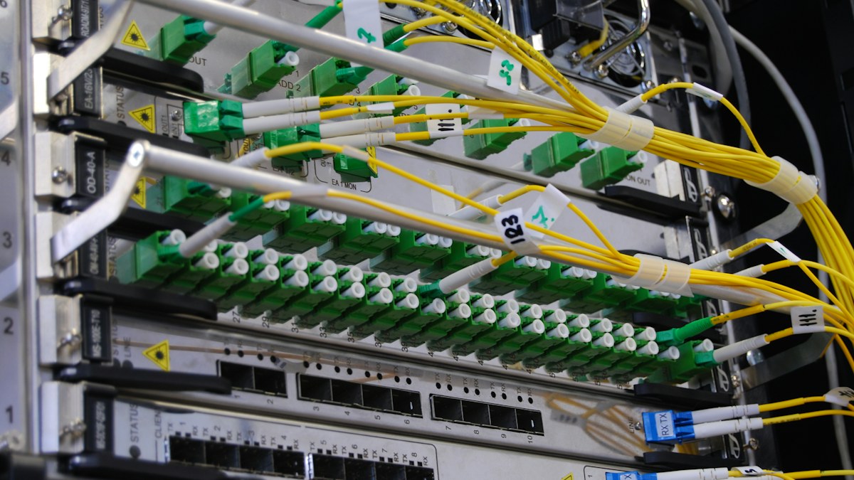 Optical Link Budget Checklist Before Choosing Long-Reach Optics
 Optical Transceiver Sample Qualification Before a Volume Order
 WDM Channel Inventory and Spare Optics Planning
 Thermal Planning for High-Density Pluggable Optics