
CMIS Module State Troubleshooting for QSFP-DD and OSFP
When a QSFP-DD or OSFP module using the Common Management Interface Specification (CMIS) is detected but the interface stays down, separate the module-wide state from the lane data-path state. A readable memory map proves management access, not that the module is in high-power mode, the intended application is selected or the data paths are initialized.
Capture the exact management context
Record the host platform, line card, port, software, module part number, firmware revision, CMIS revision reported by the host, power class and intended optical application.
Save the raw module state, fault flags, low-power status, application selection, lane state and host configuration before reseating or rebooting. Platform CLI labels can simplify or rename standard fields, so retain the exact output and consult the host documentation.
Do not write arbitrary memory-map values from an online example. Host-module control is implementation dependent, and unsupported writes can disrupt a live port.
Understand the module-wide states
The CMIS 4.0 and 5.x specifications define a module state machine that separates module-wide power control from data-path initialization. Match the procedure to the module's reported revision; earlier revisions can differ. Common observable states include:
- ModuleLowPwr: management is available while the module remains in low-power mode;
- ModulePwrUp: the module is transitioning toward high-power operation;
- ModuleReady: module-wide high-power operation is available and data paths can be initialized;
- ModulePwrDn: the module is transitioning toward low power;
- ModuleFault: the module has entered a fault state.
Remaining in ModuleLowPwr can reflect host power policy, a low-power hardware signal, software control or an incomplete transition. It is not automatically a failed laser.
Separate module ready from data-path ready
ModuleReady does not mean every lane carries traffic. The host still may need to select a supported application and initialize data paths for the intended lanes.
Check the selected application, host-side and media-side lane assignment, data rate, FEC and per-lane state. A configuration valid for one module or breakout mode may be invalid for another.
For breakout deployments, the QSFP breakout lane-mapping troubleshooting guide provides additional physical and logical isolation context.
Check host power and cooling limits
High-speed pluggables can have platform-specific power and airflow restrictions. Confirm that the slot and port support the module power class and that the chassis population follows the vendor guidance.
A host may hold the module in low power or reject activation when the port, thermal policy or software does not support the requested mode. Compare behavior on an officially supported port before declaring a module fault.
Interpret transitions and faults carefully
If the module remains in power-up, save the elapsed time, state-change flags and fault indicators. Repeated transitions can indicate host control, reset activity, unstable power, firmware interaction or a module problem.
In ModuleFault, capture all available flags before clearing or reseating. A fault code is evidence to route the investigation; it is not a substitute for the exact module and host troubleshooting procedure.
Controlled troubleshooting workflow
- Save host, software, module and CMIS identity.
- Record low-power signals, module state and fault flags.
- Confirm port power-class and thermal support.
- Verify application selection and lane mapping.
- Check data-path state and FEC per lane.
- Compare with the host's supported optics matrix and release notes.
- Perform only documented resets or power transitions.
- Substitute one verified module or port at a time.
- Recheck state, diagnostics and traffic after recovery.
Frequently asked questions
Does ModuleLowPwr mean the module is defective?
No. It can be a valid host-controlled state. Determine why the host has not completed the high-power transition.
Does ModuleReady mean the Ethernet interface should be up?
No. Data paths, application selection, FEC, remote configuration and the optical path still must be valid.
Can a host read CMIS data from an unsupported module?
Yes. Management access and operational support are separate checks.
Why does the module move repeatedly between states?
Possible causes include low-power control, resets, power policy, firmware interaction, thermal conditions or a module fault. Save the transition evidence.
Should I edit CMIS memory directly?
Only through an approved engineering procedure for the exact host and module. Routine deployment should use supported platform controls.
What should be included in a support case?
Include host/software, module and firmware identity, CMIS revision, module state, flags, application selection, lane states, power class and controlled-substitution results.
Technical sources
Confirm host management support before ordering
Share the endpoint platforms, software, port, module type, intended application, lane mode, FEC, power class and quantities. Axonode can help coordinate compatible coding, firmware traceability and sample validation requirements.
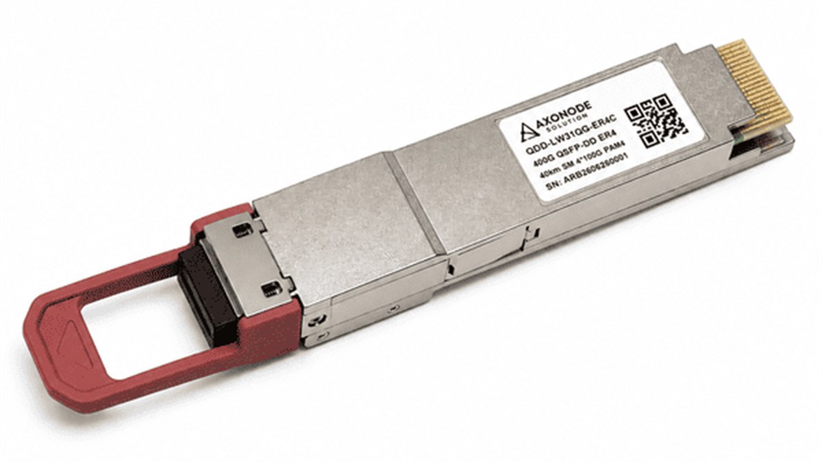 CMIS Module State Troubleshooting for QSFP-DD and OSFP
 Dirty Fiber Connector or Failed Transceiver? Controlled Fault Isolation
 Optical Transceiver Loopback Test: Isolate the Local Port Safely
 SFP Warning vs Alarm Thresholds: Decide When to Monitor or Act