
Receiver Overload on Short Fiber Links: When Long-Reach Optics Need Attenuation
A long-reach transceiver is not automatically safe on a short fiber route. If the transmitter can launch more power than the receiver accepts and the path has little loss, the receive level may exceed the overload limit. The correct decision comes from the exact transmitter range, receiver range and measured path, not from a rule that every long-reach optic needs the same attenuator.
Understand both sides of the optical budget
Most link-budget reviews focus on whether enough power reaches the receiver. A complete review checks two conditions:
- The minimum expected receive power stays above receiver sensitivity with suitable design margin.
- The maximum expected receive power stays below the receiver overload limit.
Use the maximum transmitter output and minimum path loss for the overload case. Use the minimum transmitter output and maximum path loss for the sensitivity case. Include connector, splice, passive component and measurement tolerances according to the design method.
Do not use reach labels as power limits
“10 km,” “40 km” and “80 km” describe an application or reach class under specified conditions. They do not tell you the actual receive power on a particular route.
Two modules with the same reach label can have different transmit and receive specifications. A short patch between racks can present far less loss than an outside-plant route. Some official module documentation explicitly requires attenuation below a stated distance, but that instruction applies only to the identified module and conditions.
Calculate the overload case
For a first check:
Maximum expected receive power = maximum transmit power − minimum path loss
Compare the result with the receiver overload specification. If the expected receive power can exceed the limit, calculate the attenuation needed to restore margin. Confirm units and whether specifications are per lane or total.
Do not select an attenuator from nominal distance alone. Measure the actual route when practical and use the exact datasheet. Fixed attenuation also reduces received power in the opposite design case, so verify that sensitivity margin remains adequate.
Measure both directions
Duplex paths are not always symmetrical. Connector condition, splices, patching and passive components can differ by direction. Record local transmit, remote receive, remote transmit and local receive values.
Digital optical monitoring can support diagnosis, but it is not always a calibrated substitute for a power meter. When the safety or acceptance procedure requires accurate values, use appropriate independent test equipment.
Recognize possible overload symptoms
Possible symptoms include failure to establish a stable link, high physical-layer errors, alarms or abnormal reported receive power. These symptoms are not unique to overload. Incorrect wavelength, FEC mismatch, contamination, reflections, coding or host support can look similar.
Compare the reported value with the exact overload limit and repeat the test with a controlled, approved attenuation method. Do not insert arbitrary attenuation merely because the route is short.
Install attenuation safely
Use an attenuator rated for the wavelength, connector type and power conditions. Maintain the correct connector polish; mating incompatible polish types can damage interfaces or create severe reflections.
Document attenuation value and location. Label it at the patch panel or equipment as appropriate. After installation, remeasure both directions and verify alarms, errors and traffic over the agreed observation period.
If the route includes passive CWDM or DWDM components, calculate channel-specific loss and power. The passive CWDM expansion checklist covers additional mux/demux and channel-plan controls.
Frequently asked questions
Do all 40 km or 80 km optics need attenuators on short links?
No. Check the exact transmitter maximum, receiver overload limit, minimum route loss and manufacturer instructions for the identified module.
Can receiver overload damage a transceiver?
Consequences depend on the receiver and optical power. Operate within the specified range and follow the module and host safety guidance.
Is DOM receive power enough to size an attenuator?
It may support an operational decision, but use calibrated measurement when required and account for diagnostic accuracy and variation.
Should attenuation be placed at the transmitter or receiver?
Follow the network design and component instructions. Placement affects maintenance, documentation and the power seen by each interface.
Can too much attenuation create another failure?
Yes. It can reduce receive power below the sensitivity and design-margin requirement. Recalculate both overload and low-power cases.
Why does only one direction show an overload risk?
Transmit ranges and path losses can differ by direction. Treat each direction as a separate optical budget.
Verify the power budget before selecting reach
Share exact module requirements, endpoint platforms, route length, measured loss, connectors, passive components, wavelengths and environment. Axonode can help organize a transceiver and attenuation BOM based on the real path, subject to exact component verification.
Contact Axonode for optical budget support or review the optical transceiver portfolio.
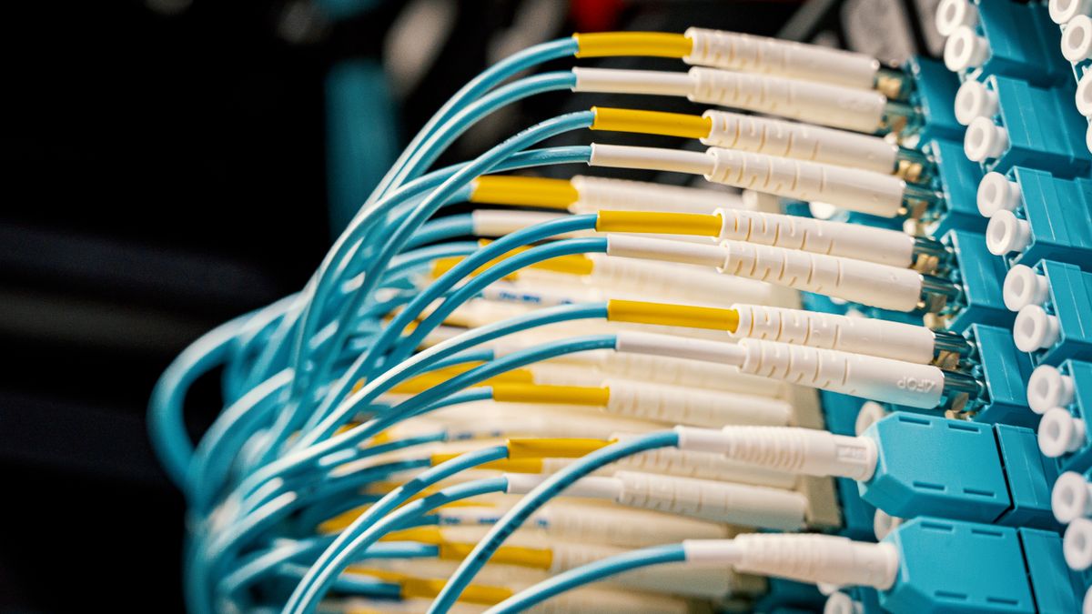 Receiver Overload on Short Fiber Links: When Long-Reach Optics Need Attenuation
 How to Build a Multi-Vendor Optics Compatibility Matrix Before Ordering
 OC-12/STM-4 SFP Replacement Guide: Match Reach, Fiber and Host Support
 Optical Transport Network Maintenance Checklist: Baselines, Alarms and Spares