
The Field Guide to Fiber Optic Network Upgrades: An Engineer's Pre-Procurement Checklist
Don't let your 100G upgrade become the next "Resume-Generating Event" (RGE). This ultimate checklist, distilled from the hard-won lessons of thousands of engineers, will help you avoid the 90% most expensive mistakes. From link budgets to MPO polarity, here's everything you need to know before you click "Purchase."
Table of Contents
- Chapter 1: Introduction
- Chapter 2: Phase 1: Planning & Assessment
- Chapter 3: Phase 2: Hardware Selection & Link Budget
- Chapter 4: Phase 3: Implementation & Testing
- Chapter 5: Conclusion & The Path to 400G
- Appendix A: Key Terminology Glossary
Introduction
We've all been there.The network traffic graphs are glowing redder by the day. The AI/ML team is demanding RDMA for their new GPU cluster. Business-side SLAs are getting tighter. The 10G network, once our workhorse, is now the bottleneck. Upgrading to 100G and beyond isn't a question of "if," but "when" and "how."
This checklist wasn't written by one person. It's the systematic distillation of thousands of engineers' late-night forum posts, project post-mortems, and the hard-won lessons behind countless "horror stories." We've gone deep into the trenches to refine that scattered, invaluable field wisdom into this structured plan of action.
It will ensure your next network upgrade is a success story to be proud of, not another horror story to be told.
Phase 1: Planning & Assessment (The "On-Paper" Phase) — Measure Twice, Cut Once
This is the most critical phase of the entire project. A mistake here costs the least to fix; clarity here ensures a smooth path forward. Remember, a successful network upgrade is 90% planning and 10% execution.
- ☐ 1. Define Needs & Baseline Performance:
- 1.1: Business Requirements Interview: Talk to business units. Quantify their bandwidth needs for the next 1-3 years, especially for high-load applications like AI/ML, virtualization, and storage.
- 1.2: Performance Baselining: Use your network monitoring tools to document current peak bandwidth utilization, latency, jitter, and packet loss. This data is the only language management understands to justify the budget.
- 1.3: Asset Inventory: Document the models, port types, and quantities of all existing core, distribution, and access switches, servers, and NICs.
- ☐ 2. Assess Cabling Infrastructure - The Network's Foundation:
- 2.1: Fiber Type Identification: Physically verify if your trunk cabling is Singlemode (SMF) or Multimode (MMF). If MMF, you must determine if it's OM3, OM4, or the older OM1/OM2. This is a hard requirement that dictates your technology path.
- 2.2: Physical Link Length Measurement: Don't Trust the Blueprints!
- (Note: Blueprints are a starting point, never the final word. Buildings undergo undocumented changes over the years, and real-world cable paths often include numerous bends and detours not shown on a 2D drawing. In one real-world case we reviewed, a team relied solely on blueprints and a measuring wheel, ignoring these accumulated bends. The result: 10 near-100-meter fiber runs all came up a "fatal inch" short, leading to a catastrophic rework and doubled costs. A Physical Path Walkthrough is a non-negotiable step.)
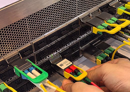
- 2.3: Connector Type Confirmation: Confirm if your current infrastructure is based on duplex LC or parallel MPO connectors.
- ☐ 3. Decide the Upgrade Path - The Fork in the Road
Your choice depends on your existing (or planned) trunk cabling. Use the matrix below to identify the best technology path for your scenario.
Cabling Scenario Upgrade Strategy Technology Solution Required Connector Max Distance Core Advantage Key Considerations / Risks Multimode Fiber (MMF) Reuse Existing Cabling 100G-BiDi LC Duplex 100m (on OM4/OM5) Highest cost-effectiveness for brownfield upgrades. • Industry First Choice: Best compatibility & aligned with future 400G BiDi roadmap.
• Hard Requirement: Must be OM4 or OM5 fiber.100G-SWDM4 (Alternative) LC Duplex 100m (on OM4/OM5) Also reuses LC cabling, offers a multi-wavelength option. • Niche Ecosystem: Limited industry adoption, unclear future upgrade path.
• Compatibility Risk: Requires strict validation with switches.Replace/New Cabling 100GBASE-SR4 MPO-12 100m (on OM4) Industry standard with the best compatibility and enables breakout applications. • Architectural Demand: Requires a "Rip & Replace" for a new MPO infrastructure.
• Fatal Risk: MPO Polarity & Gender are the most frequent failure points; must be precisely defined before procurement.Singlemode Fiber (SMF) Reuse Existing Cabling 100G-CWDM4 LC Duplex 2km Excellent price-performance for reaches up to 2km. • Scenario-Specific: Designed for <2km; link quality degrades sharply beyond this.
• Cost Advantage: Uses uncooled lasers, resulting in lower cost and power consumption than LR4.100GBASE-LR4 LC Duplex 10km The 10km standard covers most campus interconnects. • Cost Consideration: More complex technology; module cost and power are higher than CWDM4.
• Industry Cornerstone: Offers the broadest equipment compatibility.Use Parallel Cabling 100G-PSM4 MPO-12 500m Most cost-effective for breakout in high-density scenarios. • Application-Specific: Designed for <500m high-density "breakout" scenarios; not for long-haul.
• Fatal Risk: Shares the same MPO polarity & gender management complexity.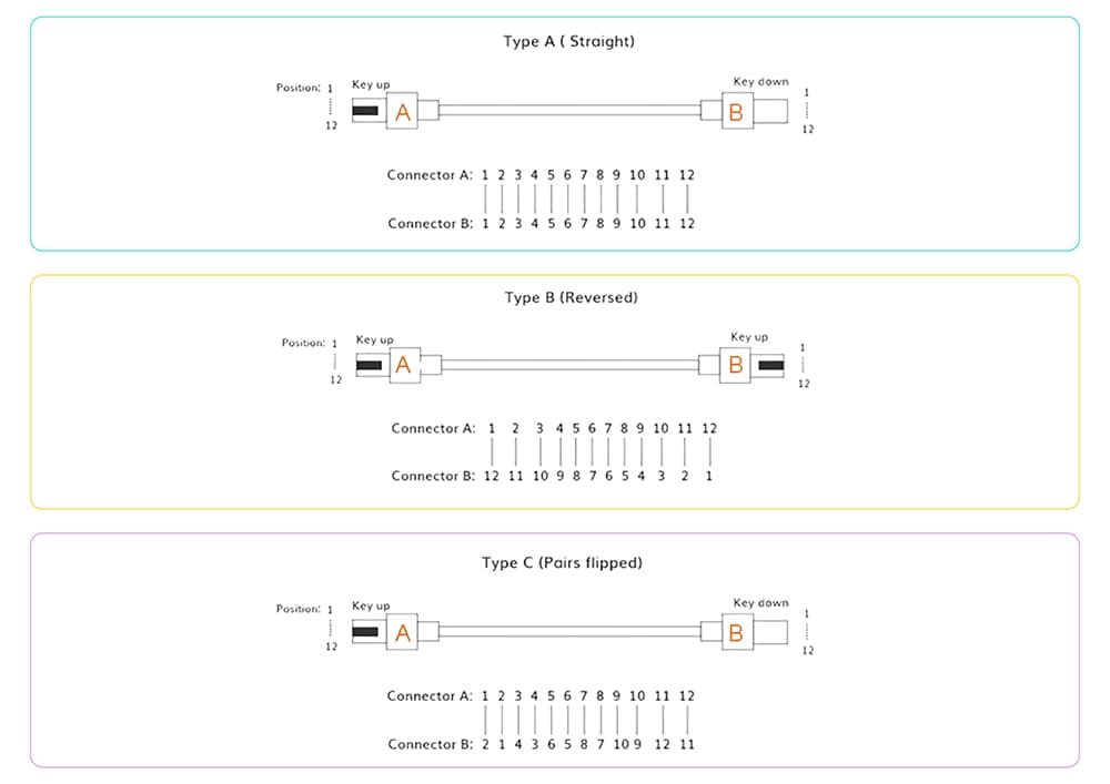
Expert's Note: The diagram illustrates the three standard MPO polarity methods (Type A, B, C). Understanding these is critical.
Type B (Reversed) is the most common for direct transceiver-to-transceiver connections, ensuring transmit (Tx) pairs correctly align with receive (Rx) pairs. A mismatch in polarity is a guaranteed link failure.Image Credit: The excellent visual explanations of MPO Polarity are adapted from Gcabling.com.
Phase 2: Hardware Selection & Link Budget (The "Procurement" Phase) — The Devil is in the Details
With your Phase 1 assessment complete, your shopping list should be clear. Now, we must select each component with the precision of a Swiss watchmaker and use mathematics to validate our design.
- ☐ 1. Select Core Components:
- 1.1: Switches: Must have QSFP28 (100G) ports. Check the official documentation for software compatibility with your chosen transceiver types (especially BiDi).
- 1.2: Transceivers & Cables:
- Intra-rack/Inter-rack (<10m): Prioritize DACs (Direct Attach Copper) or AOCs (Active Optical Cables) for the lowest cost and latency.
- Intra-Data Center (<500m): Select transceivers based on your chosen upgrade path.
- Campus (>500m): Select the appropriate SMF transceivers.
- Compatibility is Law! Procure modules that are guaranteed to be compatible with your switch brand. Demand a compatibility commitment from your vendor.
- 1.3: Server NICs: Ensure they support QSFP28 interfaces and, critically, advanced features like RDMA (RoCE v2), SR-IOV, and VXLAN offloading.
- ☐ 2. Verify the Link Budget - The Engineer's Lifeline:
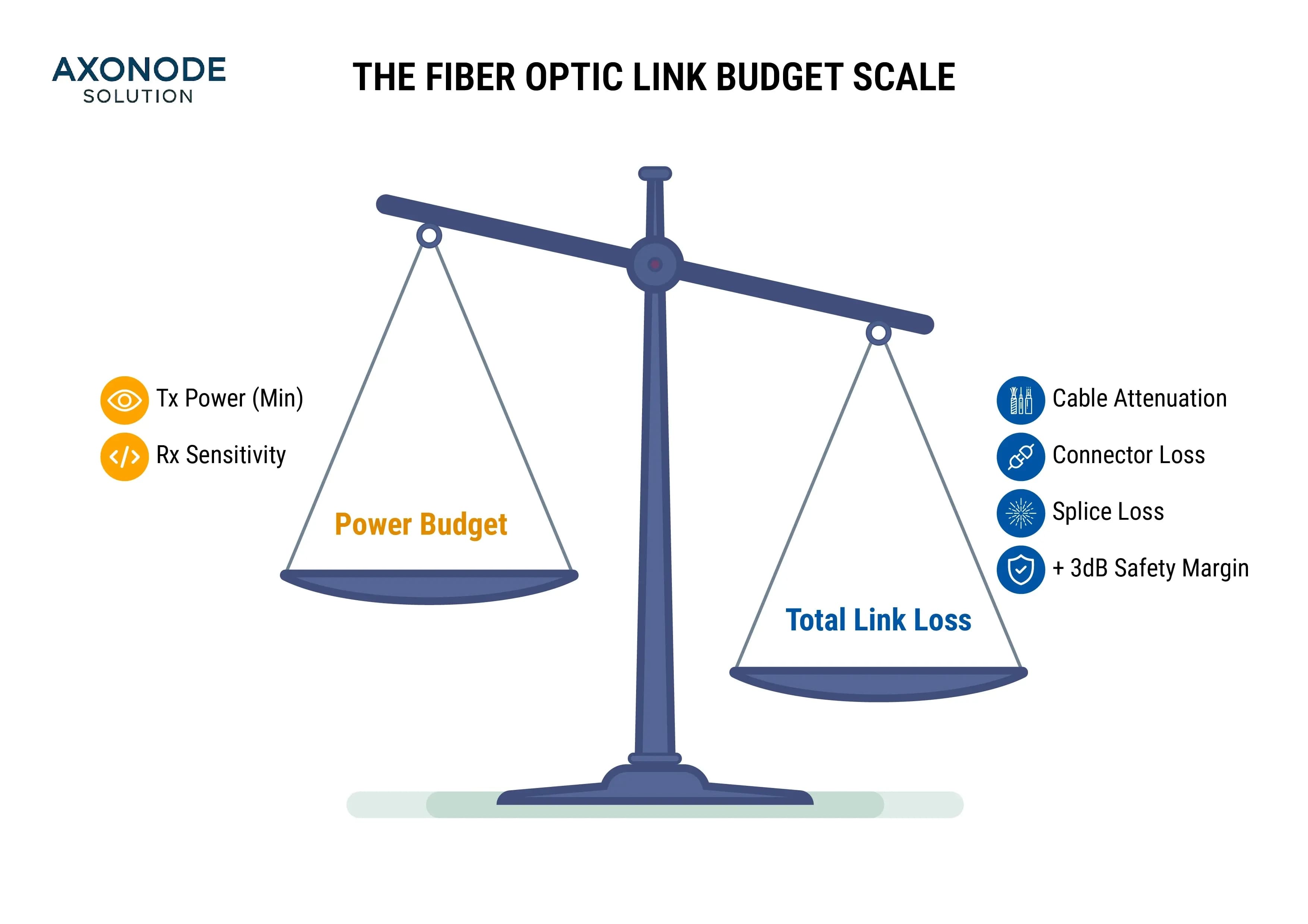
- The Golden Rule: Link Loss Budget < Power Budget. If this inequality is not true, your link is theoretically unreliable.
- 2.1: Calculate Power Budget: `(Tx Power Min) - (Rx Sensitivity)`. This data MUST come from the official transceiver datasheet.
- 2.2: Calculate Link Loss Budget: `(Total Cable Attenuation) + (Total Connector Loss) + (Total Splice Loss) + 3dB Safety Margin`.
- Further Reading & Tools(coming soon): See detailed calculation examples and download our Link Budget Calculation Template.
Phase 3: Implementation & Testing (The "Lab & Go-Live" Phase) — Trust, but Verify
Never upgrade a production network directly. The sweat you expend in the lab will save you from the blood and tears of a production outage. Expose every problem in a controlled environment.
- ☐ 1. Staging & Lab Testing:
- 1.1: Build a Minimal Testbed: Set up an end-to-end link in your lab with all the hardware you've procured.
- 1.2: Performance Benchmarking: Use tools like iperf3 to test throughput and ensure you're achieving near-line-rate performance.
- 1.3: Compatibility & Feature Validation: Check switch logs for any compatibility warnings. Test advanced features like RDMA if required.
- ☐ 2. Implementation Risk Mitigation:
- 2.1: Physical Layer Discipline:
- Clean! Clean! Clean! Every connector MUST be inspected and cleaned with professional tools before insertion. 80% of network faults are caused by contaminated end-faces.
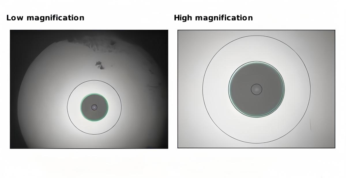
Image Courtesy: The Fiber Optic Association (FOA) - Respect the Bend Radius to avoid permanent damage to the fiber.
- Clean! Clean! Clean! Every connector MUST be inspected and cleaned with professional tools before insertion. 80% of network faults are caused by contaminated end-faces.
- 2.2: Configuration Change Discipline:
- No Manual Typing: All changes on core devices MUST be executed via a peer-reviewed script.
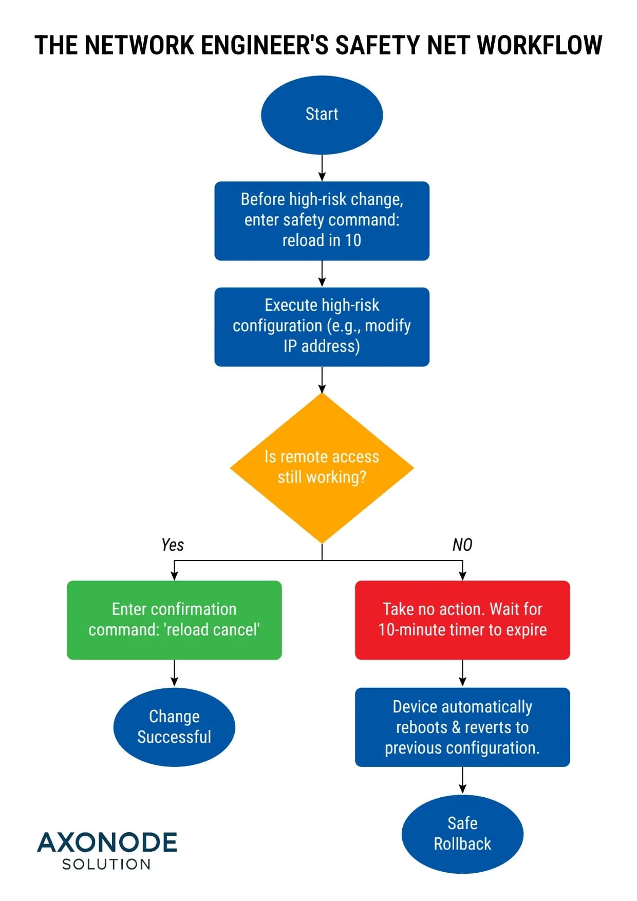
- Activate the "Safety Net": Before any high-risk remote change, you MUST use `reload in 10` (Cisco) or `commit confirmed` (Juniper) as a final failsafe.
- Further Reading(coming soon): Read the "horror stories" of nationwide outages caused by a single mistyped character.
- 2.1: Physical Layer Discipline:
- ☐ 3. Post-Upgrade Validation:
- 3.1: Tier 1 & Tier 2 Testing: Use an OLTS to verify the total link loss is within budget. Use an OTDR to troubleshoot any high-loss points.
- 3.2: Business-Level Health Check: Beyond `ping` and `iperf`, you must verify that critical business applications (e.g., ERP access, database queries) are performing as expected.
- 3.3: Update Documentation & Monitoring: Immediately update your network topology diagrams, cabling matrix, and the monitoring items in your NMS platform.
Conclusion & The Path to 400G
The upgrade from 10G to 100G is the ultimate test of planning, detail, and process. It's more than just a hardware swap; it's a comprehensive examination of your professional discipline as a network engineer.
This checklist is the distillation of the collective wisdom and scar tissue of thousands of engineers. We've extracted these critical lessons from countless forum threads, technical white papers, and project post-mortems. It can't guarantee a 100% flawless project, but it will help you evade the 90% most common and costly mistakes.
Now, download it, print it, and share it with your team. Let it be the starting point for your next upgrade kickoff meeting. Because a well-prepared upgrade is already a victory.
Looking Ahead: The Path to 400G
Once you've successfully deployed your 100G network, the path to 400G is already being paved. Future upgrades will rely less on replacing fiber and more on the evolution of transceivers and connectivity. New form factors like QSFP-DD/OSFP and higher-density VSFF connectors like SN®/MDC® will become the new stars of your technical toolkit. But no matter how the technology evolves, the core engineering disciplines you've applied from this checklist—rigorous planning, precise link budgeting, and a deep respect for the physical layer—will remain timeless.
Appendix: Key Terminology Glossary
- SLA (Service-Level Agreement): A contract defining the specific, quantifiable standards (e.g., availability, latency, packet loss) an ISP must meet.
- RDMA (Remote Direct Memory Access): A technology that allows servers to bypass the CPU and directly access each other's memory, dramatically reducing latency. RoCE v2 is the main protocol for RDMA over Ethernet.
- SR-IOV (Single Root I/O Virtualization): Allows a single physical NIC to be "sliced" into multiple virtual NICs that can be directly assigned to VMs, boosting network performance in virtualized environments.
- VXLAN (Virtual Extensible LAN): A network overlay technology used to create large-scale virtual Layer 2 networks over a Layer 3 infrastructure. VXLAN Offloading means the NIC hardware handles VXLAN encapsulation/decapsulation to free up CPU cycles.
- iperf3: An industry-standard, open-source tool for accurately measuring network bandwidth, jitter, and packet loss.
- `reload in 10` / `commit confirmed`:** A "safety net" command on Cisco/Juniper devices that allows an administrator to automatically revert a configuration change if a high-risk action causes them to lose remote access.
- OLTS (Optical Loss Test Set): A pair of devices (a light source and a power meter) used to measure the total end-to-end loss of a fiber optic link (Tier 1 certification).
- OTDR (Optical Time-Domain Reflectometer): An instrument that sends light pulses down a fiber and analyzes the reflections to locate and measure the loss and reflectance of events like connectors, splices, and breaks (Tier 2 certification).
 800G Silicon Photonics vs. EML: 2026 Cost Analysis & Buying Guide
 100G QSFP28 Selection Guide: Why Your Link is "Half-Dead" & The 2026 Missing Manual
 The Field Guide to Fiber Optic Network Upgrades: An Engineer's Pre-Procurement Checklist
 A Deep Dive into High-Speed Data Center Interconnects: A Field Guide for Engineers on DACs, AOCs & Optical Transceivers