
High-Speed Data Center Interconnects: Breakout, FEC and Cabling
A high-speed data center link succeeds only when the two hosts, port mode, lane mapping, forward error correction (FEC), cable or optical application and physical path all agree. Matching connector shapes or headline speeds is not enough.
For 100G and higher deployments, start with the supported Ethernet mode at each endpoint. Then verify whether the link is native or broken out, how electrical and optical lanes are mapped, which FEC mode is required, and whether the selected assembly is supported by both platforms.
Separate the host port from the pluggable form factor
A QSFP-family cage can support different speeds and modes depending on the platform, line card, software and port group. The module or cable also has its own application and lane structure.
Record:
- Exact chassis, switch, server or network adapter
- Line card, network module or port group
- Software or firmware release
- Native port speed and supported alternate modes
- Pluggable form factor and exact part number
- Required FEC mode
- Native or breakout topology
- Remote endpoint and its port mode
Do not infer support from another product in the same family. Port capabilities can differ by slot, ASIC, software and neighboring-port configuration.
Define the lane plan before ordering breakout assemblies
Breakout converts one parent port into several child links only when the host and selected cable or optical application implement the same lane plan.
For each breakout, document:
- Parent-port speed and mode
- Number and speed of child interfaces
- Electrical lane allocation
- Optical lane allocation where applicable
- Connector type and polarity
- Child-end form factor and host
- Whether the platform requires a port-group or profile change
- FEC requirement on every child link
A connector such as MPO does not prove that the link can break out. Parallel optics, wavelength-multiplexed optics and copper assemblies can use different lane structures even when the host cage looks similar.
Treat FEC as part of the Ethernet application
FEC is used to correct a defined level of bit errors before frames reach higher layers. The required or supported mode depends on the Ethernet application, host implementation and selected cable or optic.
A mismatch can produce a down link, an unstable link or rising corrected and uncorrected error counters. Verify the documented mode at both endpoints instead of copying a configuration from another platform.
During validation, record:
- Configured FEC at each endpoint
- Operational FEC state
- Corrected codeword or error counters when exposed
- Uncorrected errors
- Interface resets, flaps and symbol errors
- Software version and port mode used for the test
Do not disable FEC simply to make a link appear up. A link that negotiates or operates outside the documented application may fail under load or after a software change.
Match the cable plant to the optical application
For pluggable optical links, confirm fiber type, reach, connector, wavelength plan and loss budget. Parallel optical applications may require precise MPO polarity and lane continuity. Duplex applications require the correct transmit and receive path at both ends.
Inspect and clean connectors before testing. Record patch panels, adapters, cassettes and splices in the link budget. An optic's nominal reach does not include every undocumented loss in the installed path.
For DAC and AOC assemblies, verify the exact supported length and breakout construction. Measure the routed cable path rather than estimating only the distance between equipment faces.
Check power, cooling and cable-management constraints
Higher-speed pluggables and active cables can have meaningful power and thermal requirements. Confirm the platform's supported module power class, airflow direction, ambient limits and port-density restrictions.
Cable management can also become a reliability issue. Avoid excessive bend, connector strain and bundles that restrict airflow or service access. A technically supported link may still be operationally weak if technicians cannot replace it without disturbing adjacent connections.
Choose the assembly from the operational model
Use a DAC when the route is short, both hosts support the exact electrical assembly and cable bulk is manageable. Use an AOC when a fixed optical assembly provides a better cable path and the team accepts replacing the complete cable. Use separate transceivers and fiber when the link enters structured cabling, needs modular replacement or requires different endpoint coding.
This article owns the implementation details. For a speed-neutral comparison of these three assembly models, see the DAC, AOC and optical transceiver selection guide.
Stage a representative link before production
A useful staging test reproduces the real endpoint and configuration rather than testing only continuity.
- Install the intended software and port profile.
- Verify module or cable identity at both endpoints.
- Configure native or breakout mode and FEC.
- Confirm every expected child interface appears.
- Check link state, DOM readings where applicable and error counters.
- Pass representative traffic and monitor stability.
- Save the working configuration, part numbers and baseline counters.
- Test the rollback procedure and known-good spare.
Change one variable at a time when troubleshooting. Replacing the cable while also changing FEC and the port profile removes the evidence needed to identify the root cause.
Frequently asked questions
Can every 100G QSFP28 port break out to four 25G links?
No. Breakout support depends on the platform, line card, software, port group and selected assembly. Verify the exact host documentation at both ends.
Does an MPO connector identify the optical application?
No. MPO identifies a connector family, not the Ethernet lane plan. Confirm fiber count, polarity, lane mapping and the exact optical application.
Why is a high-speed link up but showing errors?
Possible causes include FEC mismatch, marginal signal integrity, dirty connectors, incorrect polarity, excessive optical loss, unsupported cable length, thermal conditions or a platform-specific issue. Preserve counters and change one factor at a time.
Can different vendors be used at opposite ends?
The optical or electrical application must interoperate, and each module or cable end must be accepted by its own host. Confirm coding, port mode, FEC, fiber and wavelength behavior separately.
Should a data center standardize on one cable type?
Standardize decision rules and approved variants rather than forcing one assembly into every route. Short fixed links, structured cabling and breakout paths can have different operational needs.
What information is needed for a high-speed interconnect BOM?
Provide both endpoint models, software, line cards, port profiles, native or breakout mode, FEC, route length, fiber and connectors, quantities, airflow limits and upgrade plan.
Confirm the complete port-to-port design
Review AOC and DAC cable options, optical transceiver options and the Data Center and AI Cloud solution. Contact Axonode with the endpoint platforms, software, port mode, FEC, breakout topology, cable path and quantities for a validated BOM review
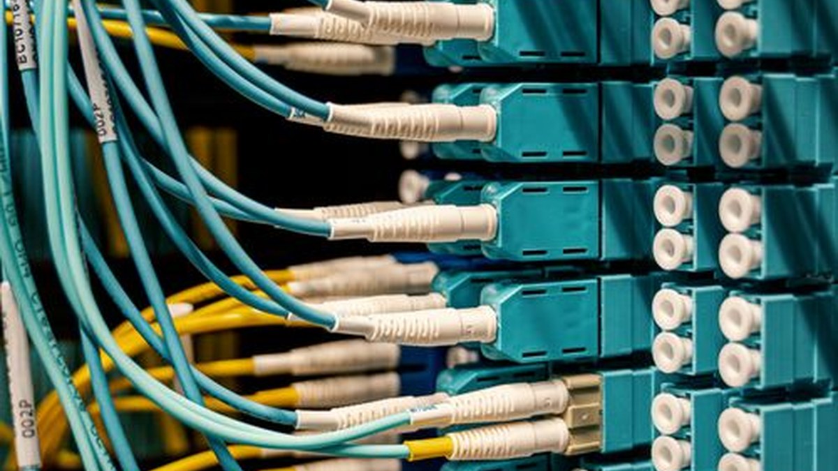 Optical Transceiver Sample Qualification Before a Volume Order
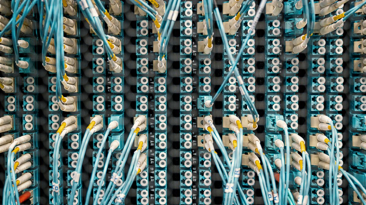 WDM Channel Inventory and Spare Optics Planning
 Thermal Planning for High-Density Pluggable Optics
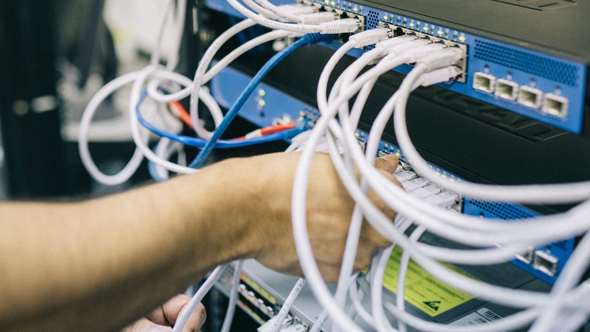 Optical Transceiver RMA Evidence Checklist: Prove the Fault Before Return