
Security Camera Transmission: Copper, Fiber or Wireless?
Use Ethernet with Power over Ethernet (PoE) when an IP camera is within the approved copper-channel distance and the cable route is controlled. Use fiber when the route is longer, exposed to electromagnetic interference, crosses buildings or needs electrical isolation. Use a wireless bridge or cellular connection when installing cable is impractical, but treat radio capacity, power and availability as engineered constraints.
The correct choice is not determined by distance alone. A security camera link must carry the required traffic, deliver or coordinate power, survive the environment and remain maintainable after installation.
Define the service before choosing the medium
Record the complete endpoint requirement:
- Camera model, codec, resolution and expected bit rate
- Number of cameras sharing each uplink
- Recording location and retention design
- Required latency and availability
- Camera power class and maximum consumption
- Route length and physical path
- Indoor, outdoor, industrial or lightning-exposed environment
- Existing copper, coaxial or fiber infrastructure
- Backup-power and surge-protection requirements
- Access for maintenance and fault isolation
Separate traffic design from power design. Fiber carries data but does not deliver electrical power to the camera. A remote fiber node may still need a local PoE switch, media converter with PoE, power supply, uninterruptible power source or another approved power arrangement.
Use direct Ethernet for controlled short links
Copper Ethernet is usually the simplest architecture for cameras located near a PoE switch. A normal standards-based Ethernet channel is commonly designed for up to 100 meters, including permanent link and patch cords. Actual PoE reach also depends on cable construction, conductor size, camera power and equipment specifications.
Direct Ethernet is a strong fit when:
- The total channel stays within the approved design limit.
- The cable can be installed away from damaging interference and high-voltage paths.
- The PoE switch supplies the camera's required power class.
- The building pathway is accessible for replacement.
- Surge, grounding and outdoor-transition requirements are addressed.
Do not treat a PoE extender as a generic permission to ignore the cable design. Extenders introduce additional powered components and device-specific distance limits. Use the manufacturer's power and distance tables for the exact camera and power source.
Use fiber for distance, isolation and difficult electrical environments
Fiber is often the safer transport between buildings, across a campus, along a perimeter or inside an environment with substantial electromagnetic interference. It can also consolidate several cameras onto one higher-capacity uplink from a remote PoE switch.
A typical architecture is:
- Cameras connect by short copper PoE runs to a remote industrial or access switch.
- The remote switch aggregates the camera traffic.
- A fiber uplink connects the remote location to the control room or core network.
- Local power, backup power, enclosure, temperature and surge requirements are designed separately.
Confirm the optical module, speed, fiber type, connector, distance, loss budget and host compatibility at both ends. If a media converter is used, verify that it supports the required Ethernet rate and operational features. Do not assume every converter passes PoE or management information.
Use a wireless bridge when the route cannot be cabled
A point-to-point or point-to-multipoint wireless bridge can cross a road, waterway, rail line or protected area without trenching. It is useful when there is clear line of sight and the radio path can be engineered.
Verify:
- Line of sight and Fresnel-zone clearance
- Channel availability and interference
- Aggregate camera throughput in normal and peak conditions
- Weather, mounting and alignment
- Encryption and network segmentation
- Local camera and radio power
- Failover expectations and maintenance access
Wireless should not be selected only because cabling is inconvenient. A changing radio environment can affect capacity and stability, so record baseline signal and throughput after commissioning.
Use cellular only when the operational model supports it
A 4G or 5G connection can support remote or temporary locations where neither fixed cable nor a reliable wireless bridge is available. The design must include coverage, data usage, addressing, cybersecurity, power and carrier availability.
Cellular is most credible when the expected camera traffic, recording behavior and data plan are quantified. Continuous high-bit-rate streaming may produce a very different operating cost and reliability profile from event-triggered transmission.
Treat legacy coax as a migration decision
Existing coaxial infrastructure may be reused with approved Ethernet-over-coax or video conversion equipment. This can reduce construction during a phased migration, but the design must verify bandwidth, distance, power delivery, connector condition and support for the exact camera system.
Reusing the cable is not automatically lower risk. Inspect the installed route and document which active conversion devices become new failure points.
Design the remote power and resilience plan
For every remote camera group, document:
- Normal power source and total PoE budget
- Backup-power duration
- Enclosure temperature and environmental rating
- Surge protection and grounding strategy
- Switch or converter management access
- Spare power supply, module and patching requirements
- Failure behavior when one uplink or power source is lost
A fiber uplink does not solve an unreliable remote power source. The data path and power path must both meet the availability target.
Validate the design before full rollout
- Build a route and endpoint inventory.
- Calculate camera and uplink traffic with operational headroom.
- Confirm the power budget for each remote group.
- Select copper, fiber or radio from the route conditions.
- Verify the exact switch, media converter, transceiver and camera compatibility.
- Stage a representative link and record throughput, errors and power behavior.
- Commission each site with labels, baseline readings and a rollback plan.
Frequently asked questions
When should a camera link move from copper to fiber?
Use fiber when the approved copper channel is insufficient, the route crosses buildings, electrical interference is significant, electrical isolation is needed or several cameras should be aggregated at a remote switch.
Can fiber deliver PoE directly to a camera?
No. Fiber carries optical data. The camera still needs an electrical power source, often through a remote PoE switch, a purpose-designed converter or local power equipment.
Is a wireless camera link less secure than a wired link?
Security depends on the complete design. A wireless link requires strong encryption, credential control, segmentation, updates and monitoring. Wired networks also require access control and secure configuration.
Can one fiber uplink support several cameras?
Yes, when a remote switch aggregates them and the uplink capacity, power, buffering and failure design support the combined traffic. Calculate the actual camera workload rather than relying on camera count alone.
Should a camera project use single-mode or multimode fiber?
Choose from the installed plant, required distance, optical application and future topology. Both endpoints must use the same supported application and connector plan.
What information is needed for a surveillance network bill of materials?
Provide camera models and quantities, site layout, route lengths, existing cable, bandwidth, power requirements, environmental conditions, switch platforms, recording design and availability target.
Confirm the transmission and power plan
Review Enterprise and Campus solutions, media converter options and optical transceiver options. For a route-specific design review, contact Axonode with the site plan, camera load, power requirements and installed cable information
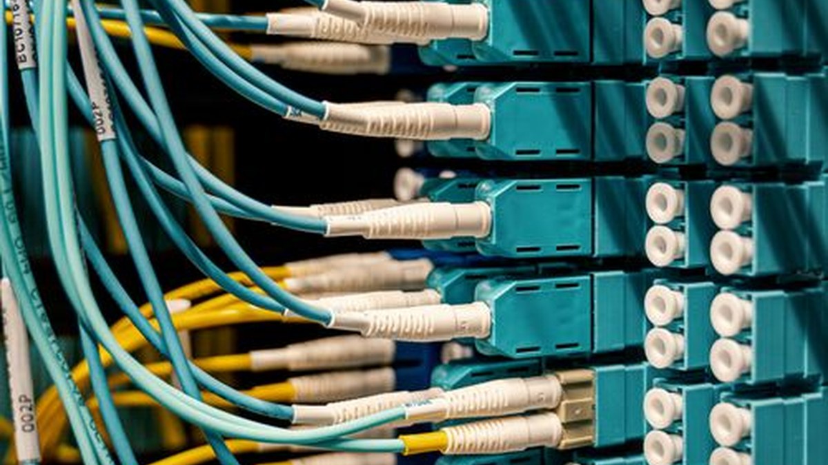 Optical Transceiver Sample Qualification Before a Volume Order
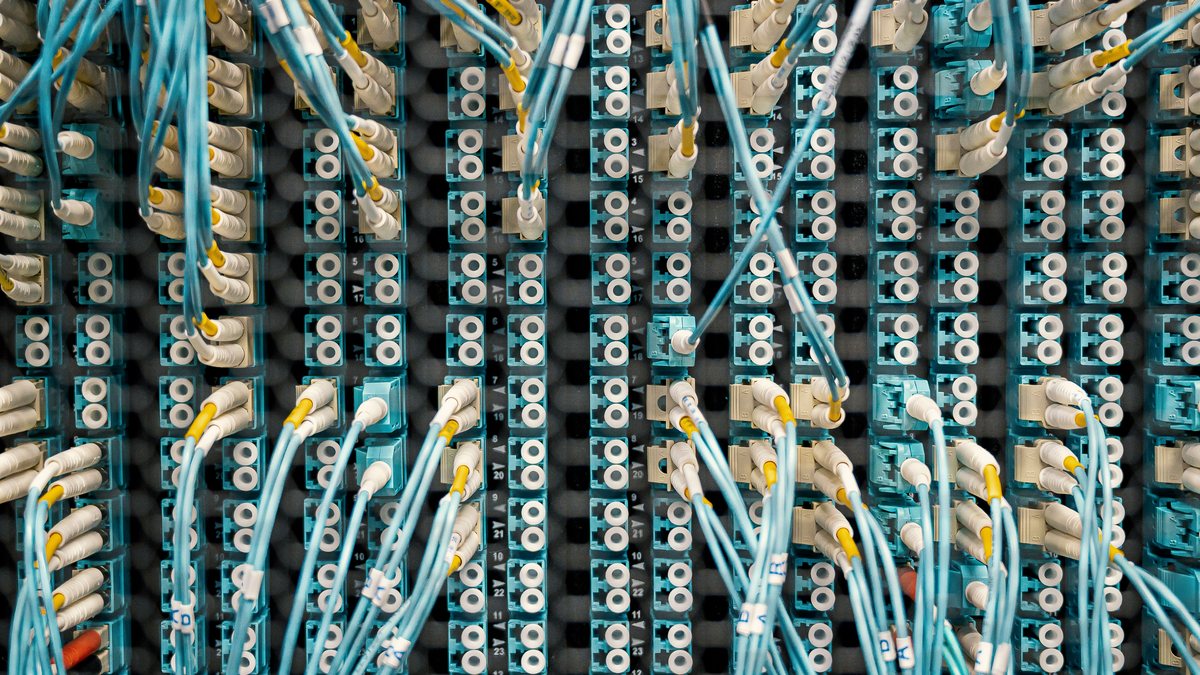 WDM Channel Inventory and Spare Optics Planning
 Thermal Planning for High-Density Pluggable Optics
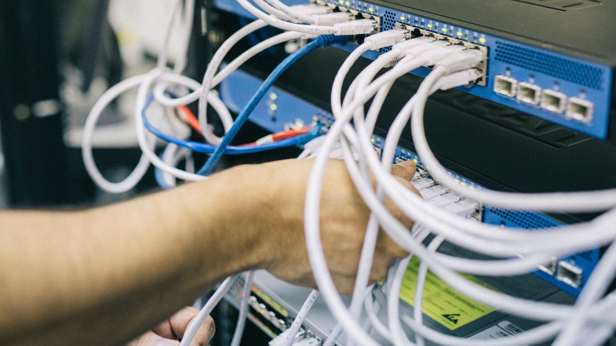 Optical Transceiver RMA Evidence Checklist: Prove the Fault Before Return